Sensors and Actuators A: Physical ( IF 4.1 ) Pub Date : 2023-08-12 , DOI: 10.1016/j.sna.2023.114543
Kuo-Ming Chang , Jian-Ming Chen , Yung-Tien Liu
|
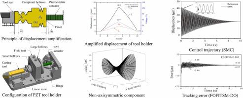
Piezoelectric actuator is widely used in various precision machines because of compact size, high precision, fast response, high stiffness, and without motion backlash, etc. However, its operational stroke is very limited. Usually, the displacement amplification mechanisms are required in practical applications. In this study, a bellows-type hydraulic displacement amplification mechanism was employed to examine the trajectory control performances based on linear and nonlinear sliding mode controls (SMCs). Fundamental experiments were performed to examine the displacement amplification ratio of 4.7 and an enlarged displacement of 42.3 µm when the applied voltage was 50 V, and to derive the system parameters and hysteresis characteristic. Since sliding mode control (SMC) has been a very popular control method featured fast response and excellent robustness for a system with model uncertainty and external disturbance, for future possible application of non-axisymmetric aspheric machining, three controllers, i.e., linear SMC, adaptive fractional order fast integral terminal sliding mode control (AFOFITSMC), and FOFITSMC based on disturbance observer (DO) were implemented in the piezoelectric tool holder system to verify the tracking control performances. The simulations for a decay sinusoidal-like waveform having a maximum amplitude of 40.3 µm were performed to machine a non-axisymmetric aspheric surface. The simulation results showed that all the controllers could smoothly follow the given trajectory with the maximum tracking errors of the peak-to-valley (PV) values of 2.96 µm, 0.315 µm, and 0.331 µm, for the linear SMC, AFOFITSMC, and FOFITSMC-DO, respectively. In addition, the results of the control practices showed that the tracking errors were with the PV values of 9.69 µm, 6.07 µm, and 6.08 µm in the beginning stage of controls for the corresponding three controllers. In the final stage of controls, the tracking errors were with the PV values of 0.15 µm, 0.03 µm, and 0.07 µm. Future works are expected to examine the tracking control performances through practical machining.
中文翻译:
波纹管式液压位移放大机构压电刀架非线性滑模控制
压电促动器具有尺寸紧凑、精度高、响应快、刚度高、无运动间隙等优点,广泛应用于各种精密机械中,但其操作行程非常有限。实际应用中通常需要位移放大机构。在本研究中,采用波纹管式液压位移放大机构来检查基于线性和非线性滑模控制(SMC)的轨迹控制性能。进行了基础实验,检查施加电压为 50 V 时的位移放大比为 4.7,放大位移为 42.3 µm,并导出了系统参数和磁滞特性。由于滑模控制(SMC)已成为一种非常流行的控制方法,对于具有模型不确定性和外部干扰的系统具有快速响应和良好的鲁棒性,对于未来非轴对称非球面加工的可能应用,三种控制器,即线性SMC、自适应在压电刀架系统中实现了分数阶快速积分终端滑模控制(AFOFITSMC)和基于扰动观测器(DO)的FOFITSMC,以验证跟踪控制性能。对最大幅度为 40.3 µm 的衰减类正弦波形进行模拟,以加工非轴对称非球面。仿真结果表明,所有控制器都能平稳地遵循给定轨迹,峰谷(PV)值的最大跟踪误差为2.96 µm,0。对于线性 SMC、AFOFITSMC 和 FOFITSMC-DO,分别为 315 µm 和 0.331 µm。另外,控制实践结果表明,对应的三个控制器在控制初期的跟踪误差PV值分别为9.69μm、6.07μm和6.08μm。在控制的最后阶段,跟踪误差的PV值为0.15μm、0.03μm和0.07μm。未来的工作预计将通过实际加工来检查跟踪控制性能。PV 值为 0.15 µm、0.03 µm 和 0.07 µm 时的跟踪误差。未来的工作预计将通过实际加工来检查跟踪控制性能。PV 值为 0.15 µm、0.03 µm 和 0.07 µm 时的跟踪误差。未来的工作预计将通过实际加工来检查跟踪控制性能。


 京公网安备 11010802027423号