当前位置:
X-MOL 学术
›
Adv. Eng. Mater.
›
论文详情
Our official English website, www.x-mol.net, welcomes your
feedback! (Note: you will need to create a separate account there.)
Low‐Temperature Polysilicon Oxide Thin‐Film Transistors with Coplanar Structure Using Six Photomask Steps Demonstrating High Inverter Gain of 264 V V−1
Advanced Engineering Materials ( IF 3.4 ) Pub Date : 2020-02-13 , DOI: 10.1002/adem.201901497 Duk Young Jeong 1 , Yeoungjin Chang 1, 2 , Won Gyeong Yoon 1 , Youngbin Do 1 , Jin Jang 1
Advanced Engineering Materials ( IF 3.4 ) Pub Date : 2020-02-13 , DOI: 10.1002/adem.201901497 Duk Young Jeong 1 , Yeoungjin Chang 1, 2 , Won Gyeong Yoon 1 , Youngbin Do 1 , Jin Jang 1
Affiliation
|
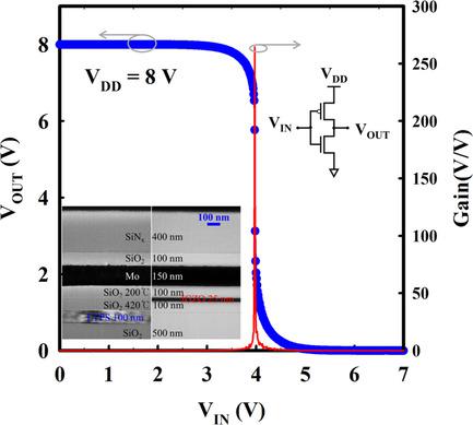
The low‐temperature polysilicon oxide (LTPO) complementary metal‐oxide‐semiconductor (CMOS) thin‐film transistors (TFTs) is fabricated by p‐type low‐temperature polysilicon (LTPS) TFT and n‐type amorphous indium‐gallium‐zinc oxide (a‐IGZO) TFT using coplanar structure. A double‐stack SiO2 layer deposited by high temperature first and then low‐temperature process is used as a gate insulator for LTPS TFT, leading to reduce the number of photomask steps. The p‐channel LTPS TFT of the fabricated LTPO circuits exhibits the field‐effect mobility (μFE) and threshold voltage (VTH) of 89.9 cm2 (V s)−1 and −5.5 V, respectively. However, the a‐IGZO TFT exhibits the μFE of 22.5 cm2 (V s)−1 and VTH of −1.3 V. Both the LTPS TFT and a‐IGZO TFT show excellent bias stability (ΔVTH of <0.1 V) and zero hysteresis voltage, which reveals the excellent interface between gate insulator and semiconductor. The LTPO CMOS inverter exhibits a gain of 264.5 V V−1 and a high noise margin of 4.29 V, and a low noise margin of 3.69 V at VDD of 8 V. Therefore, the LTPO TFT technology developed in this work can be a promising candidate for low cost, large‐area manufacturing of display, and TFT electronics.
中文翻译:

共平面结构的低温多晶硅薄膜晶体管,采用六个光掩模步骤,可实现264 V V-1的高反相器增益
低温多晶硅(LTPO)互补金属氧化物半导体(CMOS)薄膜晶体管(TFT)由p型低温多晶硅(LTPS)TFT和n型非晶铟镓锌氧化物制成(a-IGZO)使用共面结构的TFT。首先通过高温然后低温工艺沉积的双层SiO 2层用作LTPS TFT的栅极绝缘体,从而减少了光掩模步骤。p沟道低温多晶硅薄膜晶体管的制造的LTPO电路表现出的场效应迁移率(μ FE)和阈值电压(V TH 89.9厘米)2 (V S)-1分别和-5.5伏。但是,a‐IGZO TFT的μFE为22.5 cm 2 (V s)-1,V TH为-1.3V。LTPS TFT和a-IGZO TFT均显示出出色的偏置稳定性(ΔV TH <0.1 V)和零滞后电压,这显示了出色的栅极绝缘体和半导体之间的界面。LTPO CMOS反相器的增益为264.5 V V -1,高噪声裕度为4.29 V,在V DD为8 V时具有3.69 V的低噪声裕度。因此,这项工作中开发的LTPO TFT技术可能是有前途的低成本,大面积显示器制造和TFT电子产品的候选人。
更新日期:2020-02-13
中文翻译:

共平面结构的低温多晶硅薄膜晶体管,采用六个光掩模步骤,可实现264 V V-1的高反相器增益
低温多晶硅(LTPO)互补金属氧化物半导体(CMOS)薄膜晶体管(TFT)由p型低温多晶硅(LTPS)TFT和n型非晶铟镓锌氧化物制成(a-IGZO)使用共面结构的TFT。首先通过高温然后低温工艺沉积的双层SiO 2层用作LTPS TFT的栅极绝缘体,从而减少了光掩模步骤。p沟道低温多晶硅薄膜晶体管的制造的LTPO电路表现出的场效应迁移率(μ FE)和阈值电压(V TH 89.9厘米)2 (V S)-1分别和-5.5伏。但是,a‐IGZO TFT的μFE为22.5 cm 2 (V s)-1,V TH为-1.3V。LTPS TFT和a-IGZO TFT均显示出出色的偏置稳定性(ΔV TH <0.1 V)和零滞后电压,这显示了出色的栅极绝缘体和半导体之间的界面。LTPO CMOS反相器的增益为264.5 V V -1,高噪声裕度为4.29 V,在V DD为8 V时具有3.69 V的低噪声裕度。因此,这项工作中开发的LTPO TFT技术可能是有前途的低成本,大面积显示器制造和TFT电子产品的候选人。































 京公网安备 11010802027423号