Our official English website, www.x-mol.net, welcomes your
feedback! (Note: you will need to create a separate account there.)
Correction to “In Situ Ceramization of Nanoscale Interface Enables Aerogel with Thermal Protection at 1950 °C”
ACS Nano ( IF 15.8 ) Pub Date : 2024-02-06 , DOI: 10.1021/acsnano.4c00888
Quan Yuan 1 , Liwei Yan 1 , Jinfeng Tian 1 , Weiyi Ding 1 , Zhengguang Heng 1 , Mei Liang 1 , Yang Chen 1 , Huawei Zou 1
ACS Nano ( IF 15.8 ) Pub Date : 2024-02-06 , DOI: 10.1021/acsnano.4c00888
Quan Yuan 1 , Liwei Yan 1 , Jinfeng Tian 1 , Weiyi Ding 1 , Zhengguang Heng 1 , Mei Liang 1 , Yang Chen 1 , Huawei Zou 1
Affiliation
|
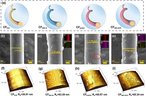
There should be “Zr” in the inserted picture of Figure 1d. The names for the inserted pictures of Figure 1e should be Zr and Si (from top to bottom), respectively. The names in Figure 2j–l should be CPASiC-0, CPA0-ZrC and CPASiC-ZrC. In Figure 4g, the unit “min” needs to be added after “10”. Additionally, the unit of the scale bar for the inserted pictures in Figure 5d–g should be “mm” not “μm”. The corrected images are demonstrated below. None of these changes affect the discussion or conclusions in the paper. The authors sincerely apologize to the readers, reviewers, and editors for these errors. Your thoughtful understanding is highly appreciated. Figure 1. (a) Diagram of fiber surfaces coated with different ceramic precursors. (b–e) SEM and (f–i) AFM images of the fiber surface with different coatings. Figure 2. (a–h) SEM of CPA0–0, CPASiC-0, CPA0-ZrC, CPASiC-ZrC. (i–l) N2 adsorption and desorption isotherms as well as BJH pore size distribution curves for different CPAs. Figure 4. (a–h) Infrared thermal images of CPA. (i) The thermal conductivity and density in this research compared with other lightweight TPS. (j) Thermal insulation mechanism of the CPA. Figure 5. (a) Back temperature of CPA during ablation. (b) XRD of the surface layer. (c) Schematic diagram of each region for CPA after ablation. SEM of the (d–g) surface layer and (h–k) pyrolysis layer. This article has not yet been cited by other publications. Figure 1. (a) Diagram of fiber surfaces coated with different ceramic precursors. (b–e) SEM and (f–i) AFM images of the fiber surface with different coatings. Figure 2. (a–h) SEM of CPA0–0, CPASiC-0, CPA0-ZrC, CPASiC-ZrC. (i–l) N2 adsorption and desorption isotherms as well as BJH pore size distribution curves for different CPAs. Figure 4. (a–h) Infrared thermal images of CPA. (i) The thermal conductivity and density in this research compared with other lightweight TPS. (j) Thermal insulation mechanism of the CPA. Figure 5. (a) Back temperature of CPA during ablation. (b) XRD of the surface layer. (c) Schematic diagram of each region for CPA after ablation. SEM of the (d–g) surface layer and (h–k) pyrolysis layer.
中文翻译:

更正“纳米级界面的原位陶瓷化使气凝胶在 1950 °C 下具有热保护”
图1d的插入图片中应该有“Zr”。图 1e 中插入图片的名称应分别为 Zr 和 Si(从上到下)。图 2j-l 中的名称应为 CPA SiC-0、 CPA 0-ZrC和 CPA SiC-ZrC 。图4g中,“10”后需要添加单位“min”。此外,图5d-g中插入图片的比例尺单位应为“mm”而不是“μm”。校正后的图像如下所示。这些变化都不会影响本文的讨论或结论。作者对这些错误向读者、审稿人和编辑致以诚挚的歉意。非常感谢您的深思熟虑的理解。图 1. (a) 涂有不同陶瓷前体的纤维表面图。 (b–e) 具有不同涂层的纤维表面的 SEM 和 (f–i) AFM 图像。图 2. (a–h) CPA 0–0 、CPA SiC-0 、CPA 0-ZrC 、CPA SiC-ZrC的 SEM。 (i–l)不同CPA的N 2吸附和解吸等温线以及BJH孔径分布曲线。图 4. (a–h) CPA 的红外热图像。 (i) 本研究中的导热率和密度与其他轻质 TPS 相比。 (j) CPA的隔热机制。图 5.(a) 消融过程中 CPA 的背部温度。 (b) 表面层的 XRD。 (c) 消融后 CPA 各区域示意图。 (d–g)表面层和(h–k)热解层的SEM。这篇文章尚未被其他出版物引用。图 1. (a) 涂有不同陶瓷前体的纤维表面图。 (b–e) 具有不同涂层的纤维表面的 SEM 和 (f–i) AFM 图像。图 2. (a–h) CPA 0–0 、CPA SiC-0 、CPA 0-ZrC 、CPA SiC-ZrC的 SEM。 (i–l)不同CPA的N 2吸附和解吸等温线以及BJH孔径分布曲线。图 4. (a–h) CPA 的红外热图像。 (i) 本研究中的导热率和密度与其他轻质 TPS 相比。 (j) CPA的隔热机制。图 5.(a) 消融过程中 CPA 的背部温度。 (b) 表面层的 XRD。 (c) 消融后 CPA 各区域示意图。 (d–g)表面层和(h–k)热解层的SEM。
更新日期:2024-02-06
中文翻译:
更正“纳米级界面的原位陶瓷化使气凝胶在 1950 °C 下具有热保护”
图1d的插入图片中应该有“Zr”。图 1e 中插入图片的名称应分别为 Zr 和 Si(从上到下)。图 2j-l 中的名称应为 CPA SiC-0、 CPA 0-ZrC和 CPA SiC-ZrC 。图4g中,“10”后需要添加单位“min”。此外,图5d-g中插入图片的比例尺单位应为“mm”而不是“μm”。校正后的图像如下所示。这些变化都不会影响本文的讨论或结论。作者对这些错误向读者、审稿人和编辑致以诚挚的歉意。非常感谢您的深思熟虑的理解。图 1. (a) 涂有不同陶瓷前体的纤维表面图。 (b–e) 具有不同涂层的纤维表面的 SEM 和 (f–i) AFM 图像。图 2. (a–h) CPA 0–0 、CPA SiC-0 、CPA 0-ZrC 、CPA SiC-ZrC的 SEM。 (i–l)不同CPA的N 2吸附和解吸等温线以及BJH孔径分布曲线。图 4. (a–h) CPA 的红外热图像。 (i) 本研究中的导热率和密度与其他轻质 TPS 相比。 (j) CPA的隔热机制。图 5.(a) 消融过程中 CPA 的背部温度。 (b) 表面层的 XRD。 (c) 消融后 CPA 各区域示意图。 (d–g)表面层和(h–k)热解层的SEM。这篇文章尚未被其他出版物引用。图 1. (a) 涂有不同陶瓷前体的纤维表面图。 (b–e) 具有不同涂层的纤维表面的 SEM 和 (f–i) AFM 图像。图 2. (a–h) CPA 0–0 、CPA SiC-0 、CPA 0-ZrC 、CPA SiC-ZrC的 SEM。 (i–l)不同CPA的N 2吸附和解吸等温线以及BJH孔径分布曲线。图 4. (a–h) CPA 的红外热图像。 (i) 本研究中的导热率和密度与其他轻质 TPS 相比。 (j) CPA的隔热机制。图 5.(a) 消融过程中 CPA 的背部温度。 (b) 表面层的 XRD。 (c) 消融后 CPA 各区域示意图。 (d–g)表面层和(h–k)热解层的SEM。


 京公网安备 11010802027423号